In this lab, a matrix library was written for our graphics environment. This library includes functions for basic matrix arithmetic, some 2D transforms such as rotation, translation and scaling and the ability to apply transform matrices to some graphics primitives. The full API for matrix functions is as specified in the Graphics Systems Specs for Lab 4. We then combined these functions with the scanfill algorithm developed in the previous lab to make some interesting pictures and animations, all of which were Star Trek based. Finally, we developed a simple viewing pipeline and used it to make our animations even more dramatic.
The Matrix Library
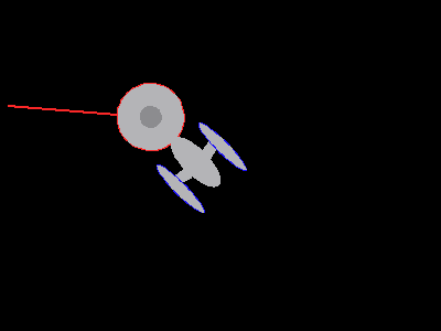
The matrix library was tested by running test code provided by Prof. Bruce Maxwell. The resulting image can be seen in Figure 1 below.
Figure 1. First required image: a spaceship rotated 135 degrees with a phaser rotated 40 degrees relative to the ship.
The Starship Enterprise Model
A model for the Enterprise was created using polygon components generated from the unit circle and the unit square only. This was done by applying scaling, shearing and translation transformations to these building blocks. The resulting model is shown in Figure 2. The model origin is located at the center of the circular disk.
Figure 2. The Starship Enterprise. Its origin is at the center of the circular disk.
Next, the Starship Enterprize was made to rotate about a planet. This was done by applying a rotation transformations (about the z-axis and centered on the planet) to all polygons in the model in increments from 0 to 2&pi radians and writing out the resulting image after each step. The animation was superimposed on a "cool" outerspace background (as an extension). The resulting animation can be seen in Figure 3 below.
Figure 3. The Starship Enterprise rotating around some monochromatic planet. Apparently chlorophyll is brighter on other planets... or maybe it's just toxic. [press the play button at the lower left corner to see animation, QuickTime required].
The 2D viewing pipeline
A simple 2D viewing pipeline was created by specifying a view transformation matrix and applying it to all elements in the image before writing the image out. By varying the nature of the view window (its bottom left corner and its dimensions) it was possible to create effects such as zooming in and out on the orbiting Starship Enterpise or panning. The resulting animation can be seen in Figure 4 below. It shows what the orbiting Starship Enterprise scene might look like from a passing spaceship.
Figure 4. View of the orbiting Starship Enterprise from a passing spaceship. Ken Burns might be proud... but probably not.
[press the play button at the lower left corner to see animation, QuickTime required].
Questions
Who did you work with on this assignment, and what tasks did each of you do?
This lab was worked on by Paul Azunre and David Wright. The matrix library functions were split into two roughly equivalent groups for each partner to implement. The remainder of the lab was done jointly.
Describe the mechanism you developed for handling the global transformation parameters and matrix.
The global transformation matrix was specified directly in main by first initializing it to the identity matrix and then applying desired transformations to it. The resulting global transform matrix was then applied to all elements in the image before writing it out (but after applying local and model transforms).
Describe the mechanism you developed for handling the viewing pipeline parameters and transformation matrix.
The viewing pipeline parameters (view dimensions and lower corner x- and y-position) were declared in main as doubles. The view transformation matrix was calculated based on these parameters (scaling and translating appropriately) and then applied to the entire image (Enterprise model plus the planet) before writing out the image.
Once you had the code in place, what was the process and how difficult was it to modify the view window and the position of the Enterprise?
Once the code was in place, it was very easy to modify the position of the Enterprise and the view window. The position of the Enterprize was changed by varying the associated model transformation matrix. The view window was modified simply by changing the width, heigth and lower left corner position of the view window. Although the current method was easy to implement it is a manual process and a more elegant method for automatically applying the transforms to all elements would be a logical next step.
If you extended this assignment in any way, describe what you did and how you did it. Include pictures, or links to pictures that show what you did.
The Enterprise was inserted onto a cool outer space background as one extension. Secondly, image sequences were animated. These can be seen from the figures already presented.
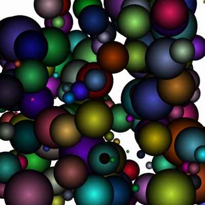
Radial fill was implemented on circles to make them appear 3D. The implementation built upon the scan-line fill algorithm for circles developed in Lab 3. The procedure is as follows:
When coloring a point within the circle, the distance from that point to the center is calculated. The point is filled in with a color that is a fraction of the fill color, with the fraction being 1 at the center and 0 at the edges i.e. fraction = [ 1 - (distance to center / radius)^2]. This makes the circle appear darker at the edges and brigther towards the center. The result is shading that gives the filled circle a 3D feel. Radially filled circles of randomly varying radii and positions are shown in Figure 5 below.
Figure 5. Radially filled circles to make them appear 3D.
Next, the radial-fill concept was used to create a more sophisticated fill implementation. Instead of being calculated relative to the circle's center, weights were calculated relative to the closest point to some specified light source. This was used to create the orbiting planet animation shown in Figure 6.
Figure 6. An orbiting planet animation created using the more sophisticated radial-fill implementation .
An additional animation was created to demonstrate the transformation matrices that were developed in this lab exercise. It demonstrates what might happen when missile gudance goes bad. This animation is shown in Figure 7 below.