CS40: Assignment #5: Hierarchical Modeling System

Paul Azunre, David Wright


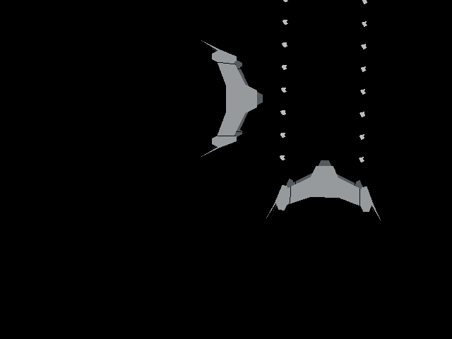
Description

In this lab, a 2D hierarchical modeling system was developed to enable us to create and draw modules. Next, a model of Clarus the Dogcow was developed. The hierarchical modeling system was then used to animate a scene that involved three independently acting formations of three Dogcows each.

The Hierarchical Modeling System

The system was tested by running test code provided by Prof. Bruce Maxwell. The resulting image can be seen in Figure 1 below.

Star Fury Fighters in space

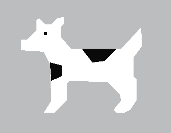
Figure 1. First required image: two space fighters doing what they do best (i.e.fighting in space).

The Dogcow Model

The model was created by loading an image of a Dogcow into an image editing application and reading off the coordinates of several points along its body. These coordinates were then used to set points for polygons that, when combined in a DogCow module with the appropriate colors, bore some resemblance to the original image of Clarus. The resulting model is shown in Figure 2 below.

Our version of Clarus the Dogcow.

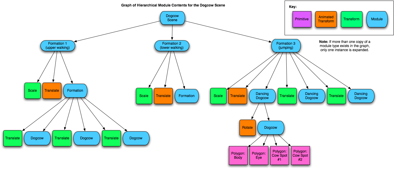
Figure 2. Our Dogcow model. Moof!

The Animated Dogcow Scene

The Dogcow model was used to create a scene which involved three formations of Dogcows acting independently. This task was made easy by the functioning hierarchical modeling system. After the Dogcow model was created as a module, it was used as the foundation for formations of multiple Dogcows. Three formation modules were created with three Dogcow submodules each. Two of the formation modules were nearly identical, consistng of three Dogcows in a triangular formation. Both formations actually use the same underlying triangular formation submodule and merely apply different scaling and translations. The formation submodule, in turn, consists of three Dogcow submodules, each with a translation applied to specify its location in the formation. The ability to repeatedly use the same module, but apply different transformations to create more complex scenes, is the power of the hierarchical modeling system. The final formation adds a new layer in the hierarchy by putting the Dogcow modules in another module with a rotation before adding three of these rotated "Dancing Dogcow" submodules to the formation which has its own set of translations. The three formations were then added to the scene module to complete the scene. The resulting hierarchy can be seen graphically in Figure 3. Some translations were made dependent on a parameter which could be changed with a loop, allowing for the generation of a sequence of images suitable for use in an animation.

Graph of hierarchical modules used in Dogcow scene.

Figure 3. Hierarchy of the Dogcow scene (click on the image for a larger version).

To produce an animation, each formation was scaled, translated and/or rotated independently to produce desired motion effects. The first formation was made to run from left to right across the top of the view window, the second was made to run from right to left across the bottom, while the third was made to do backflips in the center. The resulting animation is shown in Figure 4 below.


Figure 4.
A bunch of Dogcows having fun in their natural habitat (QuickTime Movie).

Questions

  1. Describe the operation of your DrawStructure routine.

    The Module_draw routine operates by traversing all elements in the module from head to tail. A switch statement is used to indicate which actions need to be performed when different element types are encountered. The function has state varibales for a current color, a Local Transformation Matrix (LTM), a Global Transformation Matrix (GTM), and a View Transformation Matrix (VTM). Appropriate actions are as follows:

    • When a matrix element is encountered, the current Local Transformation Matrix (LTM) is left multiplied by the encountered matrix to create a new LTM.
    • When an Identity element is encountered, the LTM is set to the identity matrix regardless of its current value.
    • When a Line, Polyline, Polygon or Point element is encountered, the curent LTM, GTM, and VTM are applied to the primitive object and it is then drawn into the image using an appropriate primitive drawing function and the current color.
    • When a Color element is encountered, the current drawing color is set to the new color in the element data.
    • When a submodule is encountered, a new Global Transformation Matrix (GTM) is calculated as the product of the current GTM and the current LTM (in that order). The Module_draw routine is then called recursively on the submodule.

  2. Describe how you made use of hierarchical modeling when you made one or more of your images. Show the code for your main program where you create the module, and then somehow show a representation of the module as a graph.

    Please refer to The Animated Dogcow Scene section above. To draw the scene, code very similar to that used by Professor Maxwell to generate the first required image was used.


  3. What extensions did you do for this assignment, how did you do them, and how well did they work?
    Animating the Dogcow sequence was an extension. The results are visible in Figure 4, and things seemed to have worked pretty well.

    Additionally, a few functions were added to the API to facilitate relatively easy use of circles and ellipses as primitives. The functions work by generating appropriate polygons to represent a specified ellipse or circle primitive. The polygon is then added to the model like any other polygon module. With the heirarchical modeling system rotations are easy, so a function was finally added to specify an angle for the ellipse. Figure 5 demonstrates the use of these functions.

Clarus goes for a swim.

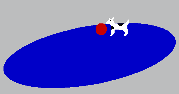
Figure 5. Clarus chases a ball into a pool to demonstrate the addition of circle and ellipse primitive support.

  • A bunch of additional animations were created to demonstrate the hierarchical modeling techniques learned in this lab. The animation below shows three missile instances directed as a target.

  • The animations below show flies swarming around a strawberry. The animation on the right is slightly different in that flies leave for the strawberry every once in a while [click on animations for larger versions].


API Additions

  • void Ellipse_setAngled(Ellipse *e, Point tc, double ta, double tb, double a);
    Similar to the standard Ellipse_set() function, but allows the user to specify and angle offset for the ellipse's a-axis relative to the x-axis in radians.
  • void Module_addCircle(Module *md, Circle *c);
    Generates and adds a polygon representing the Circle primitive to the selected module.
  • void Module_addEllipse(Module *md, Circle *c);
    Generates and adds a polygon representing the Ellipse primitive to the selected module.
 
 
© Paul Azunre and David Wright, 2006