E26/CS40 Lab 8: Z-Buffer Algorithm
Paul Azunre, David Wright
Description
This lab involved the addition of the Z-buffer algorithm to the capabilities of our graphics environment. The main purpose of this algorithm is hidden surface removal. This is achieved by keeping track of the depth co-ordinate of each pixel already written to the image and comparing it with the depth co-ordinate of the corresponding pixel of an object that needs to be rendered into the scene. Depth storage space is allocated whenever an image is initialized. This space was included as an array of floats in the image structure. The size of this array needs to be equal to the product of the number of rows and columns of the associated image. When a pixel that is about to be written to the image is found to have a z-coordinate smaller than the corresponding z-coordinate stored in the z-buffer, it is written to the image. This is done because such a condition indicates that the current point is closer to the observer than the point currently is the z-buffer and is therefore what the observer would see. In this case, the z-buffer is updated to the z-coordinate of the pixel that was just written to the image. No action is taken otherwise.
Required Image
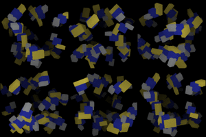
The Z-buffer algorithm was tested by running example code provided by professor Bruce Maxwell. The resulting animation is shown in Figure 1. Cubes further away from the viewer were shaded darker to make the depth dimension easier to appreciate.

Figure 1.
Cubism animation (click on the animation for a larger version).
de Casteljau Algorithm for Bezier Curves
It was decided that the implementation of some type of spline was overdue.
Drawing of Bezier curves was enabled using the de Castel algorithm. This algorithm approximates a spline by subdividing a line segment between adjacent control points. This division is performed N-1 number of times, where N is the number of control points. The division is governed by a set of weights assigned to each control point, which are in turn determined by a single parameter u. By varying the parameter from 0 to 1, the entire curve may be traced out.
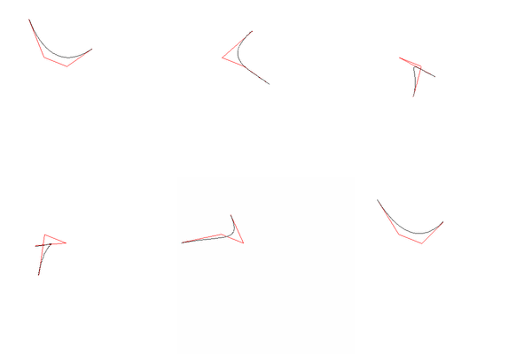
An animation which shows both the convex hull (red) and the spline (black) can be seen in Figure 2 below. Some control points were varied in order to show that the algorithm works correctly.
Figure 2. A Bezier spline drawn using the de Castel Algorithm. The convex hull of the spline is shown in red, while the spline is black.
(click on the animation for a larger version).
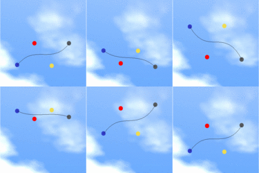
A cooler animation was created do demonstrate how the shape of the Bezier curve changes as the control points change in position. In the animation shown in Figure 3, the centers of the colors circles are the control points. These are made to follow out-of-phase simple harmonic motion. A couple of characteristics of a Bezier spline are apparent from the animation. In particular, it can be easily observed that the curve passes through the first and last points and not those in between. The whole animation is inserted into a cool background to give it a more aesthetic feel. Again, please click on the animation for a larger version of the animation.

Figure 3. Animation demonstrating the change in the shape of the Bezier spline as the control points follow out-of-phase simple harmonic motion.
Questions
- We know z varies inversely with x and y for perspective projection. How does z vary relative to x and y for parallel projection?
Z varies linearly with x and y in parallel projection.
- What extensions did you do for this assignment, how did you do them, and how well did they work?
The de Castel Algorithm for drawing Bezier Curves was implemented. Please refer to the appropriate section above for a more complete description. Some animations were created to demonstrate several characteristics of the Bezier curve.
The API
For the most part, the API is the same as that given in the Graphics Environment Specification.
- Spline *SplineCreate(int N, Point *list);
This function returns a pointer to a spline that has N control points specified by point array list. - void SplineSet(Spline *S, int N, Point *list);
This function sets an existing spline (*S) to have N control points specified by point array list. - void BezierSplineDraw(Spline *S, int res, Image *src, Pixel c);
This function draws a Bezier Curve (*S) into the image src using color c and resolution res. Resolution simply indicates the number of steps in u (from 0 to 1) that should be taken while drawing the spline.
