E26/CS40 Lab 7: 3-D Hierarchical Modeling
Paul Azunre, David Wright
Description
This lab extends the 3-D transformations developed in Lab 6 to the hierarchical modeling system developed in Lab 5.
Transformations
For this lab, the five 3-D tranformations developed for Lab 6 were applied to the modules used in the hierarchical system. The list of the transformations is as follows:
- Scale
- Translate
- Rotate about the X-axis
- Rotate about the Y-axis
- General rotation
As both the 3-D viewing pipeline and hierarchical modeling systems were working, the implementation was straightforward. For each desired tranformation, a new function was added to the module library. The next steps are virtually idenitical to those used for the 2-D hierarchical system. Each function starts with an idenity matrix, applies the appropraite 3-D transform from the matrix library developed in lab 6, and then adds this matrix as an element to the passed module parameter. When the scene is drawn, all elements added after the transform are affected by it.
A Cube Primitive
Additionally, a function was added to allow for easy creation of cube modules with polygon sides, essentially a 3-D primitive. The first step to achive this was to define the eight points corresponding to corners of a unit cube centered at the origin. The next step is to create triangle polygons to represent sides of the cube. Triangles are used rather than rectangles because they are easier to handle in graphics system, largely due to the fact that the three points used to define a triangle are guaranteed to br planar. Each side requires two trinagle polyons, for a total of six. Groupings of three corner points are used to define each triangle. The order in which the triangle points are entered is chosen so that, when looking directly at the box side from a position outside the box the points are in a clockwise order. This consistent ordering will allow for implementation of back plane culling later as explained below. After all the triangle polygon elements are added to a module we have a unit cube which can be used as a building block with the transforms to generate a variety of rectangularish shapes.
Ordering of points for triangle polyons that are part of a 3-D object can matter because it can be important to be able to find normals pointing out of an object, as in back plane culling. Depending on whether the triangle points are listed clockwise or counter-clockwise, the same algorithm for determining a normal vector using the cross product of vectors obtained from the triangle vertices will yield a result into or out of the plane (in a closed 3-D object this means into or out of the object). If the ordering is not consistent, there will be no way to tell which normal it is, making useful things like backplane culling impossible.
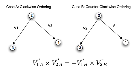
Figure 1.
Triangle point ordering matters for 3-D objects.
A full list of the functions added can be seen in the API section.
Images Demonstrating the Cubes and Transformations

Figure 2.
A cube being rotated about the x-axis.

Figure 3.
The same cube being rotated about the y-axis.
Figure 4.
The cube rotating about an arbitrary axis.
Figure 5.
The cube translating 4 units in x and 1 in y.

Figure 6.
The cube scales down in x- and y-dimensions while expanding in z.
Cubism
An animation was created using the test code provided by Professor Bruce Maxwell. The resulting animation is shown in Figure 7 below.
Figure 7. Required "cubism" animation [click on animation for a bigger version]
Liang-Barsky Algorithm and Framed Cubism
Next, the ability to draw framed cubes was added. While enabling this function, it was realized that no method of clipping lines had yet been developed. This prompted the implementation of Liang-Barsky line clipping algorithm in 2D.
This algorithm works by expressing a line in parametric form, and testing whether its beginning and ending points lie within the view window. This involves finding the intersection points of the line with each of boundary of the view window (four boundaries in 2D, six in 3D). Each intersection point can be expressed as a single parameter u. Intersection points that are found to be on the line (0<u<1) replace the beginning and ending points. Intersection points that are not on the line are ignored. Vertical and Horizontal lines are treated as special cases, and testing whether they lie within the view window is trivial.
The algorithm was implemented as a function called LineClip2D. The line drawing function calls it before drawing each line, and it returns the clipped line as well information on whether the line should be drawn or not. Refer to "The API" section for a more detailed description of the usage of LineClip2D.
Clipping was done in 2D only. While it is trivial to extend the implementation to 3D, it was not done because for our purposes, 2D clipping is sufficient. This is because in our system, clipping only needs to be performed after the perspective view transformation is applied (which converts every 3D object into its 2D form).
The clipping algorithm was used to create the framed cubism animation shown in Figure 8 below. The framed cubes were created using the function Module_cubeFrame, which is described in more detail in "The API" section.
Figure 8. Framed "cubism" animation. Line clipping is performed using the Liang-Barsky Algorithm. [click on animation for a bigger version]
Unit Octahedron Module
Additionally, two octahedral module functions were written: one to produce a filled octahedron, and one to produce an octahedral frame. These were used to generate the animations shown in Figure 9 below. Note: " Diamonds are forever ".


Figure 9. Octahedral frame (on the left) and a filled octahedron.
Questions
1. What extensions did you do for this assignment, how did you do them,
and how well did they work?
The Liang-Barsky line clipping algorithm was implemented. Functions were written to produce a filled octahedron, and an octahedral frame. For more detailed descriptions, please refer to the appropriate sections above.
The API
For the most part, the API is the same as that given in the Graphics Environment Specification.
-
void Module_scale(Module *md, double sx, double sy, double sz);
Adds an arbitray 3-D scale matrix on to the passed module. -
void Module_translate(Module *md, double tx, double ty, double tz);
Adds an arbitray 3-D translation matrix on to the passed module. -
void Module_rotateY(Module *md, double cth, double sth);
Adds a 3-D rotation about the Y-axis matrix on to the passed module. -
void Module_rotateX(Module *md, double cth, double sth);
Adds a 3-D rotation about the X-axis matrix on to the passed module. -
void Module_rotateXYZ(Module *md, Vector *u, Vector *v, Vector *w);
Adds a 3-D rotation about an arbitary axis specified by the vectors to the passed module. -
void Module_cube(*md);
Allows for easy addition of a cube to a scene. Upon return, the module *md contains 12 triangular polygons representing the faces of a unit cube centered at the origin. -
void Module_cubeFrame(*md);
Allows for easy addition of a cube frame to a scene. Upon return, the module *md contains 12 lines representing the edges of a unit cube centered at the origin. - void LineClip2D(line *l,int rows, int cols, int *dflag);
Takes as input a pointer to a line and clips it to the view window of size rows x cols. Integer pointer dflag is set to 0 when the line is completely outside the view window and should not be drawn, and 1 otherwise.